
Understanding ITU-T Fiber Standards: G.652, G.655, G.657 Explained
Understanding ITU-T Fiber Standards: G.652, G.655, G.657 Explained
Published: 2026-05-20
Why Fiber Standards Matter
The ITU-T (International Telecommunication Union - Telecommunication Standardization Sector) defines the global standards for optical fibers. When you specify “G.652.D” or “G.657.A2” in your procurement documents, you’re referencing a precisely defined set of optical, mechanical, and environmental performance characteristics.
Understanding these standards helps you:
- Choose the right fiber for your specific application
- Ensure interoperability between different manufacturers’ products
- Optimize network performance and cost
- Future-proof your infrastructure
The ITU-T Single-Mode Fiber Family
ITU-T Recommendation G.65x defines the family of single-mode optical fibers. Here’s what each standard means in practice:
G.652 — Standard Single-Mode Fiber
The workhorse of the fiber world. Over 95% of all deployed fiber is G.652.
| Sub-category | Water Peak | PMD Link Value | Typical Use |
|---|---|---|---|
| G.652.A | Present | ≤ 0.5 ps/√km | Legacy, O-band only |
| G.652.B | Present | ≤ 0.2 ps/√km | Legacy, O-band + C-band |
| G.652.C | None | ≤ 0.5 ps/√km | Full spectrum, low-cost |
| G.652.D | None | ≤ 0.2 ps/√km | Modern standard, full spectrum, 10G/40G capable |
Key Characteristics (G.652.D):
- Zero-dispersion wavelength: ~1310nm
- Attenuation: ≤ 0.35 dB/km @ 1310nm, ≤ 0.22 dB/km @ 1550nm
- Mode field diameter: 8.6-9.5 μm @ 1310nm
- PMD: ≤ 0.2 ps/√km (enables 40G transmission)
When to use G.652.D: Almost always. It’s the default choice for metro, access, long-haul, and FTTH networks. Only deviate from G.652.D when you have a specific technical requirement.
G.655 — Non-Zero Dispersion-Shifted Fiber (NZ-DSF)
G.655 shifts the zero-dispersion point outside the 1550nm window (C-band), where EDFA amplifiers operate. This provides a small, controlled amount of dispersion that suppresses four-wave mixing (FWM) — a nonlinear effect that degrades DWDM signals.
| Sub-category | Dispersion @ 1550nm | Typical Use |
|---|---|---|
| G.655.C | 1.0-10.0 ps/(nm·km) | Long-haul DWDM |
| G.655.D | 1.0-10.0 ps/(nm·km) | Long-haul DWDM, lower PMD |
| G.655.E | 1.0-10.0 ps/(nm·km) | Extended L-band DWDM |
When to use G.655:
- Long-haul DWDM systems with 10G+ channels and close wavelength spacing
- Replacing or extending existing G.655 infrastructure
- When FWM is a confirmed impairment limiting system performance
When NOT to use G.655:
- Metro/access/FTTH networks (use G.652.D)
- Most new long-haul builds (modern coherent optics manage dispersion digitally)
- Short-reach applications (cost premium not justified)
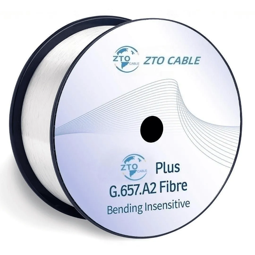
G.657 — Bending-Insensitive Fiber
G.657 fibers are engineered for superior macrobend performance — critical for FTTH indoor routing, dense cabinet installations, and any scenario where fiber must navigate tight corners.
| Sub-category | Min Bend Radius | MFD Compatible with G.652? | Typical Use |
|---|---|---|---|
| G.657.A1 | 10mm | Yes | FTTH drops, indoor cabling |
| G.657.A2 | 7.5mm | Yes | Tight FTTH routing, MDU |
| G.657.B2 | 7.5mm | No (different MFD) | Specialty in-building |
| G.657.B3 | 5mm | No (different MFD) | Extremely tight routing |
Key specification — Macrobend loss at 1625nm:
- G.657.A1: ≤ 0.75 dB for 1 turn at 10mm radius
- G.657.A2: ≤ 1.5 dB for 1 turn at 7.5mm radius
When to use G.657:
- Always use G.657.A1 or A2 for FTTH drop cables — the bend tolerance makes the difference between a working installation and a failed one when cables are routed through walls and around corners
- Indoor fiber cabling in MDUs (Multi-Dwelling Units)
- Dense fiber management trays in data centers
- Any application with tight bend constraints
Multimode Fiber Standards (G.651.1 / OM1-OM5)
While single-mode dominates outdoor and long-distance applications, multimode fiber remains important for short-reach data center and enterprise applications:
| Type | Core Size | Bandwidth @ 850nm | Max 10G Reach | Max 100G Reach | Color |
|---|---|---|---|---|---|
| OM1 | 62.5 μm | 200 MHz·km | 33m | — | Orange |
| OM2 | 50 μm | 500 MHz·km | 82m | — | Orange |
| OM3 | 50 μm | 1500 MHz·km | 300m | 100m | Aqua |
| OM4 | 50 μm | 3500 MHz·km | 400m | 150m | Aqua/Violet |
| OM5 | 50 μm | 3500 MHz·km | 400m | 150m (SWDM) | Lime Green |
How to Read a Fiber Specification Sheet
When evaluating a fiber datasheet, focus on these critical parameters:
Optical Parameters
- Attenuation (dB/km): Lower is better. For G.652.D, ≤ 0.22 dB @ 1550nm is standard.
- Dispersion (ps/nm·km): Matters for high-speed (>10G) and long-distance (>40km) links.
- PMD (ps/√km): ≤ 0.2 for 10G, ≤ 0.1 for 40G, ≤ 0.04 for 100G.
Geometrical Parameters
- Mode Field Diameter (MFD): Must match for low-loss splicing. G.652 and G.657.A are compatible; G.657.B may not be.
- Cladding Diameter: 125 μm ± 1 μm (industry standard)
- Core/Cladding Concentricity: ≤ 0.6 μm for low splice loss
Mechanical Parameters
- Proof Test Level: ≥ 0.69 GPa (100 kpsi) — ensures fiber is free of critical flaws
- Coating Diameter: 245 μm ± 10 μm (standard primary coating)
- Dynamic Fatigue: ≥ 20 (ensures long-term mechanical reliability)
Fiber Selection Quick Reference
| Application | Recommended Fiber | Reason |
|---|---|---|
| Long-haul backbone (>100km) | G.652.D or G.655 | Low attenuation, DWDM capable |
| Metro/access network | G.652.D | Good balance of cost and performance |
| FTTH feeder/distribution | G.652.D | Standard fiber, widely available |
| FTTH drop cable | G.657.A2 | Bend-insensitive for residential routing |
| MDU indoor cabling | G.657.A2 | Tight bend tolerance for in-building routing |
| Data center (short reach) | OM4/OM5 MMF | Lower transceiver cost for <150m |
| Data center (inter-building) | G.652.D | Single-mode for >150m links |
| Harsh environment (OTDR monitoring) | G.652.D | Proven reliability, wide temperature range |
Conclusion
For most new fiber optic deployments, the decision is straightforward:
- Use G.652.D for all outdoor, metro, long-haul, and FTTH feeder/distribution segments
- Use G.657.A2 for all FTTH drop cables and indoor-routed segments
- Use OM4/OM5 only for short-reach data center applications where transceiver cost savings matter
- Consider G.655 only for long-haul DWDM specific applications or legacy network extension
Related Products
Frequently Asked Questions
1. What is the difference between G.652.A and G.652.D?
The key difference is the water peak. G.652.A and B have a water peak around 1383nm caused by OH- ion absorption, limiting them to the O-band and C-band. G.652.C and D eliminate the water peak, enabling operation across the full spectrum from 1260nm to 1625nm (including the E-band). G.652.D is the modern standard and the default choice for new deployments.
2. Can G.657 fiber be spliced to G.652 fiber?
Yes, G.657 fibers (both A1 and A2) are fully backward compatible with G.652.D. They have the same mode field diameter and can be fusion spliced to G.652.D fibers with standard splicing programs and negligible loss penalty. This is essential for FTTH deployments where G.657 drop cables connect to G.652 distribution cables.
3. Is G.655 fiber still relevant in 2026?
G.655 (NZ-DSF) remains relevant for specific long-haul DWDM applications where minimizing dispersion across the C-band is critical. However, for most new deployments, G.652.D with advanced dispersion compensation or coherent optics has become the preferred solution. G.655 is typically specified only when replacing or extending existing NZ-DSF infrastructure.